The first part of the lab helped me become familiar with programming the SparkFun RedBoard Artemis Nano with the Arduino IDE. The second part introduces communication between the Artemis microcontroller and a host computer via Bluetooth Low Energy (BLE) using Python and Jupyter notebooks.
Lab 1A
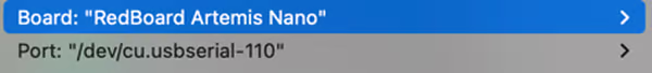
After installing the Arduino IDE and the board package, I selected the SparkFun RedBoard Artemis Nano as the active board and connect it to the correct serial port.
Then, I verified the toolchain by compiling and uploading the example cases.
Blink Example
This tests the programming of the board and the LED control. A blue light is flashing on the board.
Serial Example
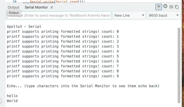
This tests USB serial communication. After printing the setup message, it echoes the input string to the serial monitor.
Analog Read Example
This tests temperature sensing. After grasping the board, the sensor warms up, raising the temperature from approximately $\approx 33,100$ to approximately $\approx 33,500$. Video Here
PMD Microphone Example
This test checks the microphone's functionality. When I speak into the microphone, the loudest frequency increases from $\approx 200$ to $\approx 1,000$. Video Here
Lab 1B
Configurations and Setup
I installed Python 3.13.2 using pyenv. Then, I created a virtual environment in the project directory. I use this environment to run the provided Jupyter notebooks for BLE communication.
pyenv install 3.13.2
pyenv virtualenv 3.12.3 FastRobots_ble
Next, I activated the virtual environment from the project folder
pyenv activate FastRobots_bleNext, I installed the following packages
pip install numpy pyyaml colorama nest_asyncio bleak jupyterlabNow, I was able to start the Jupyter server
jupyter labTo deactivate the virtual environment, run:
deactivateAfter downloading the lab codebase, I loaded and flashed ble_arduino.ino onto the Artemis board. Once uploaded, the board began advertising over BLE and printed its Bluetooth MAC address to the serial monitor.

Then I generate a new BLEService UUID and replace the original one in ble_arduino.ino.
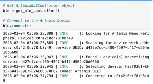
#define BLE_UUID_TEST_SERVICE "d427e7cc-c400-4597-b417-d564e20d6600"Both the Artemis MAC Address and BLEService UUID were also copied into ble_python/connections.yaml to allow the host controller to connect to the correct device.
After creating the ArtemisBLEController, we can connect to the Artemis Device. Both the Jupiter notebook and the Arduino serial monitor print the success messages.

Codebase Understanding
The provided code consists of two coordinated components and creates a clear client–server architecture
-
Arduino Peripheral Device (ble_arduino)
This runs directly on the Artemis with the key modules:- ble_arduino.ino:
- handle_command(): main command dispatcher
- Loop (): checks whether new data has been written
- BLECStringCharacteristic.h: supports string-based BLE communication
- RobotCommand.h: parses command strings into typed values
- EString.h: safely constructs outgoing strings
- ble_arduino.ino:
-
Python Host Controller (ble_python)
This runs on the laptop and provides a high-level interface for BLE communication.
The ArtemisBLEController abstracts BLE operations:- send_command(): sends commands. The types are listed in cmd_types.py
- receive_*(): eads characteristics
- start_notify() handles asynchronous data streams
Bluetooth Communication Workflow
- The Artemis advertises a BLE service.
- The laptop connects as a BLE central device.
- Python writes a command string to the writable characteristic.
- The Arduino parses and executes the command.
- The board returns results via a notify/read characteristic.
- Python receives and processes the data.
Task 1: ECHO Command
After the string is extracted, the response is constructed using the EString helper and transmitted via the string characteristic.
        case ECHO:

            char char_arr[MAX_MSG_SIZE];

            // Extract the next value from the command string as a character array
            success = robot_cmd.get_next_value(char_arr);
            if (!success)
                return;

            tx_estring_value.clear();
            tx_estring_value.append(char_arr);
            tx_characteristic_string.writeValue(tx_estring_value.c_str());

            Serial.print("Robot says -> ");
            Serial.print(tx_estring_value.c_str());
            Serial.println(":)");

            break;
Python sends the command using:
ble.send_command(CMD.ECHO, "HiHello")The board returned the augmented string on the serial monitor:

Task 2: SEND_THREE_FLOATS
Three floating-point values are sent from Python as a command string separated by delimiters. The Arduino tokenizes the string and parses each value as a float.
        case SEND_THREE_FLOATS:
            float fl_a, fl_b, fl_c;

            // Extract the next value from the command string as a float
            success = robot_cmd.get_next_value(fl_a);
            if (!success)
                return;

            success = robot_cmd.get_next_value(fl_b);
            if (!success)
                return;

            success = robot_cmd.get_next_value(fl_c);
            if (!success)
                return;

            Serial.print("Three Floats: ");
            Serial.print(fl_a);
            Serial.print(", ");
            Serial.print(fl_b);
            Serial.print(", ");
            Serial.println(fl_c);
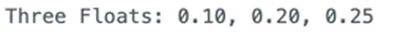
break;ble.send_command(CMD.SEND_THREE_FLOATS, "0.1|0.2|0.25")Then, the values are printed to the serial monitor.
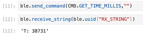
Task 3: GET_TIME_MILLIS
I added this new command to the enum CommandTypes and the handle_command() function. When the command is received, the handler reads the internal timer using millis(), converts the value to a string, and sends the string back.
        case GET_TIME_MILLIS:
            unsigned long t;
            t = millis();

            tx_estring_value.clear();
            tx_estring_value.append("T: ");
            tx_estring_value.append((int)t);
            tx_characteristic_string.writeValue(tx_estring_value.c_str());

            Serial.println(tx_estring_value.c_str());
            break;
Python retrieves the value:
Task 4: Notification Handler
Instead of polling for data repeatedly, I created a BLE notification handler in Python to receive incoming values. When Artemis writes to a characteristic, the callback function is triggered immediately. If the value is a timestamp, it is recognized and collected into a list.
timestamps = []
def time_notification_handler(sender, data: bytearray):
    s = ble.bytearray_to_string(data)
    if s.startswith("T:"):
        t = int(s[2:])
        timestamps.append(t)
print("Time(ms) =", t)ble.start_notify(ble.uuid["RX_STRING"], time_notification_handler)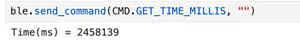
Task 5: Per-Message Transmission
I created a loop that repeatedly requested timestamps from the board for two seconds using the GET_TIME_MILLIS command. The notification handler on the laptop compiled these timestamps into a list. I calculated the number of received messages to estimate the effective data transfer rate.
timestamps = []
duration = 2.0
start = time.time()

while time.time() - start < duration:
    ble.send_command(CMD.GET_TIME_MILLIS, "")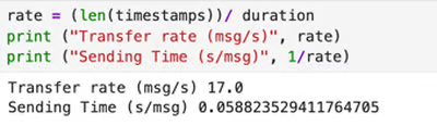
From these measurements, I determined an average rate of approximately 17 messages per second.
Task 6 – Batch Transmission
I initialized a global array to store timestamps and prevent overfill by recording the sample count.
const int SAMPLE_LEN = 500;
unsigned long time_buffer[SAMPLE_LEN];
int sample_count = 0;
bool collecting = false;
I added the START_COLLECT_DATA command to begin collecting timestamps.
After calling SEND_TIME_DATA, the board will stop sampling, iterate every element in the array, and transmit in batch.
        case START_COLLECT_DATA:
            sample_count = 0;
            collecting = true;
            break;

        case SEND_TIME_DATA:
            collecting = false;

            for (int i = 0; i < sample_count; i++) {
                tx_estring_value.clear();
                tx_estring_value.append("T: ");
                tx_estring_value.append((int)time_buffer[i]);
                tx_characteristic_string.writeValue(tx_estring_value.c_str());
                delay(3);
            }
            break;
During sampling, the time_buffer will record time in the loop.
void loop () {
    //……
    while (central.connected()) {
            // Send data
            write_data();

            // Read data
            read_data();

            if (collecting && sample_count < SAMPLE_LEN) {
                time_buffer[sample_count] = millis();
                temp_buffer[sample_count] = getTempDegF();
                sample_count++;
            }
        }
}
In the host computer, we send command to control the sampling time.
timestamps = []
ble.send_command(CMD.START_COLLECT_DATA, "")
time.sleep(duration)
ble.send_command(CMD.SEND_TIME_DATA, "")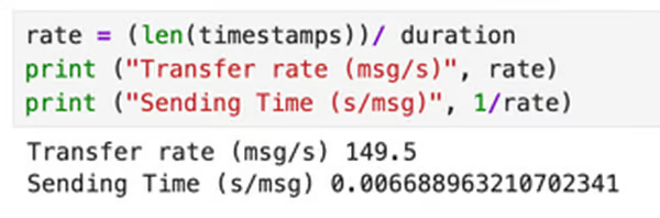
Using this approach, I measured a transfer rate of approximately 150 messages per second . This corresponds to an effective data throughput of about 1400 bytes per second (1.4 KB).
Task 7: Temperature Recording
I added a second global array to store temperature.
unsigned long temp_buffer[SAMPLE_LEN];The temperature is sampled at the same time as the clock time in the loop.
Similar to Task 6, after calling GET_TEMP_READINGS, the board stops collecting and transmitting data in batches of "T: <time>|F:<temp>".
        case GET_TEMP_READINGS:
            collecting = false;

            for (int i = 0; i < sample_count; i++) {
                tx_estring_value.clear();
                tx_estring_value.append("T: ");
                tx_estring_value.append((int)time_buffer[i]);
                tx_estring_value.append("|F:");
                tx_estring_value.append((int)temp_buffer[i]);
                tx_characteristic_string.writeValue(tx_estring_value.c_str());
                delay(3);
            }
            break;
The Python callback function retrieves and records the data.
times = []
temps = []
def temp_notification_handler(sender, data: bytearray):
    s = ble.bytearray_to_string(data).split("|")
    if len(s) == 2:
        time = int(s[0][2:])
        temp = float(s[1][2:])
        times.append(time)
        temps.append(temp)
        print ("T:", time, ", F:", temp)

ble.start_notify(ble.uuid["RX_STRING"], temp_notification_handler)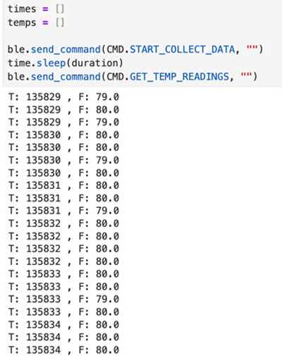
Task 8: Comparison of Per-Message vs. Batch Transmission
Task 5 uses a request–response communication pattern. A full round-trip cycle takes approximately 0.058 seconds per message (≈17 messages per second). Because each message is only 8–10 bytes, this corresponds to an effective throughput of roughly 150 bytes per second. This method is simple and provides immediate feedback, since each data point is available as soon as it is measured. So, it is convenient for interactive debugging and quick testing. However, the repeated BLE round-trip overhead significantly limits the data rate, making this method inefficient for continuous sensing or high-frequency sampling. The slow update rate can introduce latency and reduce the system’s ability to respond quickly.
Task 6 separates sampling from communication using buffering. Instead of transmitting each measurement immediately, the board first stores data locally in RAM and sends the entire batch afterward. In this case, the limiting factor is no longer BLE communication but the execution speed of the microcontroller’s main loop. Sampling takes only about 0.006 seconds per data point, achieving an effective throughput of approximately 1.4 KB/s, which is nearly nine times faster than the per-message method. This significantly improves efficiency and reacts to feedback faster. The tradeoff is that the data is not available to the laptop in real time, so this method is less suitable for live monitoring.
However, this appoach is limited by memory capacity The Artemis board has 384 kB (≈393,216 bytes) of RAM. Each timestamp–temperature pair requires 8 bytes, allowing a theoretical maximum of about 49,000 samples before memory is exhausted.
Discussion
This lab clearly shows how BLE overhead can significantly reduce the amount of time available for sampling. There are always trade-offs between the amount of time available and the amount of information that can be obtained.
At first, I was confused about the interaction flow of the two platforms. After reading all the relevant code patiently, I understood.
I also had difficulty with the data types and their conversion between platforms. It took a long time to understand what ESting.h was doing.
Collaboration
I referenced Lucca’s and Akinfolami's site for code debugging (the data type for GET_TIME_MILLIS) and website formatting. I used ChatGPT for Task 7 debugging and website formatting/development