This lab focuses on integrating and evaluating a Time-of-Flight (ToF) distance sensor (VL53L1X) with the Artemis microcontroller to measure distances to nearby objects. The objective is to characterize the sensor’s performance—including range, accuracy, and measurement speed—and to implement efficient code that collects time-stamped distance data and transmits it via Bluetooth.
Pre-Lab
I2C Address
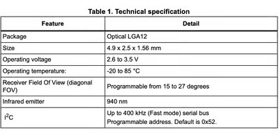
According to the VL53L1X Time-of-Flight sensor datasheet, the default I2C address of the sensor is 0x52. Since both sensors initially power up with the same address, they cannot be addressed independently on the same I2C bus without additional configuration.
Two ToF Sensors
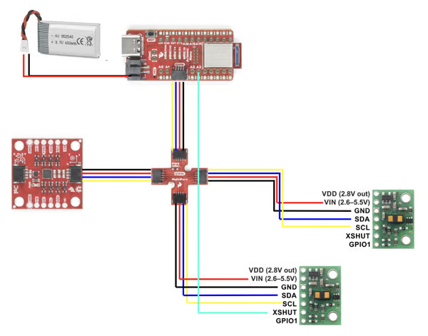
Both ToF sensors will be connected through the Qwiic connectors, which share the same I2C bus (SDA and SCL are wired in parallel across connectors J1–J4). Because of this shared bus architecture, connecting two sensors with the same default address would create an I2C address conflict.
To resolve this issue, I will control the XSHUT pin of one sensor using a GPIO pin on the Artemis board. During system startup, the Artemis will hold one sensor in shutdown by pulling its XSHUT pin LOW, allowing communication with the first sensor. After initializing the first sensor, the program will assign it a new I2C address. The Artemis can then release the second sensor from shutdown and initialize it using the default address. This approach allows both sensors to operate simultaneously on the same I2C bus while avoiding address conflicts.
Sensor Placement
For a fast autonomous robot, the placement of the ToF sensors strongly affects the performance of the reactive control system. Ideally, two sensors would be placed at the front-left and front-right of the robot to detect obstacles symmetrically. However, the tight structure and large wheels of the RC car limit the available mounting space.
Therefore, I decided to place:
- One ToF sensor at the center of the front bumper, facing forward. This sensor will measure the distance to obstacles in front of the robot and can be used for speed control and braking.
- A second ToF sensor on the side of the car, oriented approximately 90° relative to the direction of motion. This sensor can measure the distance to a nearby wall or surface, enabling wall-following behavior and steering adjustments in structured environments such as hallways.
A limitation of this configuration is that the robot will not detect obstacles on the opposite side, since only one lateral sensor is used. As a result, objects approaching from that side or obstacles positioned outside the sensor field of view may be missed.
Wiring
Rather than being soldered, I2C sensors should have detachable connections to the bus. This allows for easy replacement or reconfiguration. Batteries also use detachable connectors, such as JST, so they can be safely removed for charging.
In terms of hardware layout, the IMU should be mounted near the center of the robot to improve measurement stability. Since the Artemis board and battery are also located near the center, a 50 mm cable is sufficient for connections between the IMU, breakout board, and Artemis. The two ToF sensors will require 100 mm cables so they can be mounted near the edges of the chassis. The wires will be soldered from the back side of the ToF boards to reduce mechanical interference and improve cable management.
Lab
Hardware Setup
Based on the wiring plan from the prelab sketch, both ToF sensors were connected to the Qwiic breakout board. The wiring followed the Qwiic cable color convention:
- Red – VIN
- Black – GND
- Blue – SDA
- Yellow – SCL
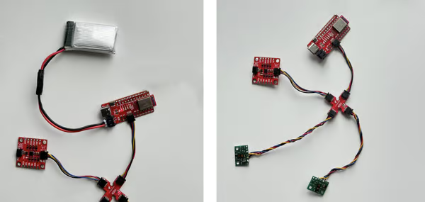
To improve reliability, the wires were twisted together to reduce potential electromagnetic interference and keep the signal lines organized. Additionally, heat-shrink tubing was used to insulate the exposed portions of the wires and provide mechanical protection for the solder joints.
To power the Artemis board independently, I soldered a JST connector onto a 650 mAh battery. The JST connector on the battery has reversed color polarity compared to the Qwiic wiring, so I carefully verified the VIN and GND connections before attaching it to the board. With the battery connected, the Artemis can operate untethered, allowing the robot to run without a USB-C connection while still transmitting data over Bluetooth.
I2C Address Detection
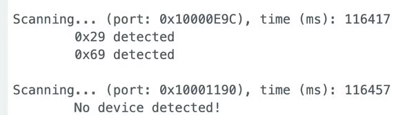
To identify devices on the I2C bus, I connected one IMU and one ToF sensor to the breakout board and ran the Example05_wire_I2C scanning program. The scan detected two I2C devices:
0x29– VL53L1X ToF sensor0x69– ICM-20948 IMU
Initially, the ToF address seemed inconsistent with the 0x52 address listed in the VL53L1X datasheet. However, this difference occurs because the I2C bus typically uses 7-bit addresses, while datasheets list the 8-bit address.
In I2C communication, the 8-bit write address is obtained by shifting the 7-bit address left by one bit:
0x29 << 1 = 0x52
Therefore, the 0x29 address reported by the scanner is correct, and it corresponds to the 0x52 address documented for the VL53L1X sensor.
ToF Distance Modes
The VL53L1X ToF sensor provides three ranging modes: Short, Medium, and Long. These modes trade off maximum detection range, measurement latency (update rate), and immunity to ambient light noise.
- Short Mode (~1.3 m) provides the lowest latency and fastest update rate, allowing the robot to react quickly to nearby obstacles. It also has better noise immunity and higher accuracy at short distances. However, the maximum detection range is limited, which reduces the robot’s ability to detect obstacles far ahead.
- Medium Mode (~3.0 m) provides a balance between range and measurement speed. It allows for a longer detection distance than short mode while maintaining moderate latency. This mode is available when using the Pololu VL53L1X library and may be useful in situations where both reaction speed and detection distance are important.
- Long Mode (~4.0 m) provides the largest detection range, allowing the robot to detect obstacles farther away. However, this mode has higher latency and is more sensitive to ambient light noise, which may introduce measurement errors in bright environments.
For the final robot, I chose to use Long Mode. Since the robot can travel at approximately $3 m/s$, it would cover the entire $1.3 m$ range of short mode in about $0.4$ seconds, leaving very little time for the control system to react. Additionally, the robot requires extra distance to slow down or stop safely. Therefore, a longer detection range is more important than achieving the highest measurement accuracy at very short distances.
Although long mode is more sensitive to ambient light noise, the robot will primarily operate indoors in a lab environment, where lighting conditions are relatively controlled. Because of this, the increased noise sensitivity is unlikely to significantly affect performance, while the longer detection range provides more time for obstacle detection and avoidance.
ToF Sensor Testing
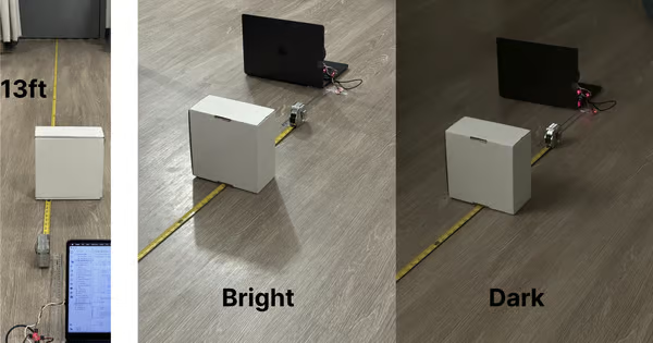
To evaluate the performance of the VL53L1X sensor in Long Mode, I measured distances from 0.25 ft to 13 ft (15 measurement points). For each distance, I recorded 100 measurements over approximately 5–10 seconds. I repeated the experiment under two different lighting conditions: Dark indoor & Bright indoor.
Accuracy and Measurement Behavior
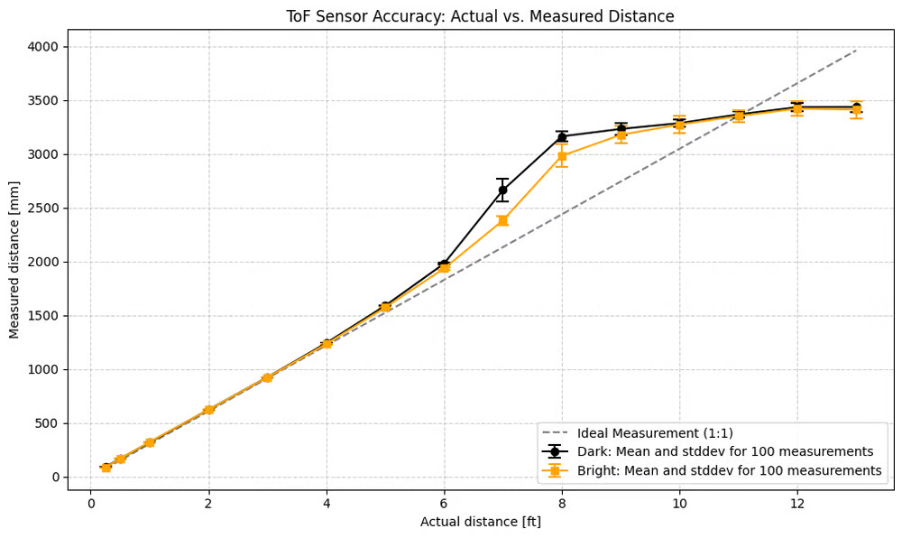
This plot shows the mean measured distance compared to the truth distance, along with the standard deviation from 100 measurements for both lighting conditions.
From the results, the sensor closely follows the ideal 1:1 measurement line at shorter distances. However, beyond approximately 6 ft, the measurements begin to deviate from the ideal line. The sensor gradually underestimates the actual distance, and the deviation increases as the target distance approaches the maximum range.
This behavior occurs because long mode prioritizes detection range over precision. As the distance increases, the reflected signal becomes weaker, which increases measurement uncertainty and bias.
Despite this drift at longer distances, the sensor remains very consistent at short distances. For example, measurements at 0.25 ft show very small variance across repeated samples, indicating high repeatability and stability.
Effect of Lighting Conditions
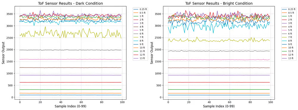
Comparing the two lighting conditions, the bright environment introduces slightly larger fluctuations in the measurements. This is expected because the VL53L1X uses infrared light, and stronger ambient lighting can introduce additional noise in the reflected signal.
However, the difference between bright and dark environments is relatively small for most distances, indicating that the sensor maintains reasonable robustness to ambient light in indoor environments.
Sampling Rate Behavior
I also measured the sensor update rate at different distances:
| Distance | Samples in 5 s |
|---|---|
| 0.25 ft | 106 |
| 0.5 ft | 86 |
| 1 ft | 53 |
| 2 ft | 53 |
| 1–13 ft | ~110 |
These results correspond to an approximate sampling rate between 10–21 Hz.
The variation in sampling rate is mainly caused by the internal ranging algorithm of the VL53L1X. The sensor dynamically adjusts the integration time and signal processing depending on the strength of the reflected signal. When the sensor receives a weaker signal (i.e 2m), it may require longer integration times to obtain a reliable measurement, which reduces the update rate.
Two ToF Sensor
To operate two VL53L1X sensors on the same I2C bus, I used the XSHUT pin to control the startup sequence and avoid an address conflict. Since both sensors power up with the same default address (0x29), I first held Sensor 2 in shutdown by pulling its XSHUT pin LOW. This allowed the Artemis to initialize Sensor 1 normally. I then changed Sensor 1’s I2C address to 0x2A, after which I enabled Sensor 2 by setting its XSHUT pin HIGH and initialized it with the default address.
#define XSHUT_PIN A3    //// XSHUT pin for the second sensor

SFEVL53L1X distanceSensor1;
SFEVL53L1X distanceSensor2;

int distance_buffer1[SAMPLE_LEN];
int distance_buffer2[SAMPLE_LEN];
void setup(){
SERIAL_PORT.println("VL53L1X Qwiic Test");
// Turn off Sensor 2 to prevent I2C address conflicts
pinMode(XSHUT_PIN, OUTPUT);
digitalWrite(XSHUT_PIN, LOW);
delay(10);
// Initialize Sensor 1
while (distanceSensor1.begin(WIRE_PORT) != 0)
{
SERIAL_PORT.println("ToF Sensor 1 failed to begin. Retrying in 500ms...");
delay(500);
}
// Change Sensor 1's I2C address to 0x2A
distanceSensor1.setI2CAddress(0x2A<<1);
// Turn on Sensor 2 (Default 0x29)
digitalWrite(XSHUT_PIN, HIGH);
delay(10);
// Initialize Sensor 2
while (distanceSensor2.begin(WIRE_PORT) != 0)
{
SERIAL_PORT.println("ToF Sensor 2 failed to begin. Retrying in 500ms...");
delay(500);
}
distanceSensor1.setDistanceModeLong();
distanceSensor2.setDistanceModeLong();
SERIAL_PORT.println("Both ToF Sensors online!");
}After both sensors were initialized, I configured them to run in long distance mode. During operation, the program continuously checked whether both sensors had new data available using checkForDataReady(). Once data was ready, the code retrieved the distance measurements from each sensor and stored them along with a timestamp in buffers.
void loop() {
// ........
if (collecting && sample_count < SAMPLE_LEN) {
loop_count++;
if (distanceSensor1.checkForDataReady() && distanceSensor2.checkForDataReady()){
int current_dist1 = distanceSensor1.getDistance();
distanceSensor1.clearInterrupt();
int current_dist2 = distanceSensor2.getDistance();
distanceSensor2.clearInterrupt();
time_buffer[sample_count] = millis();
distance_buffer1[sample_count] = current_dist1;
distance_buffer2[sample_count] = current_dist2;
sample_count++;
}
}
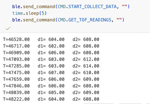
}To verify that both sensors were working simultaneously, I transmitted the collected data through BLE to the host computer. The output shows two independent distance measurements (d1 and d2) being reported at the same timestamps.
Tof Senser Speed
Same with the previous code, I use polling in the main loop to continuously check the sensor state.
if (distanceSensor1.checkForDataReady() && distanceSensor2.checkForDataReady()) ensures that the program only reads the ToF data when the sensor reports that new data is ready.
To evaluate the update rate, I ran the system for 10 seconds, repeating the experiment 10 times. In each run, the system collected approximately 106 samples.
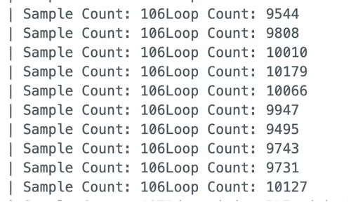
This corresponds to a sensor update rate of approximately: $\frac{106}{10} \approx 10.6 \text{ Hz}$
During the same period, the total loop count was around 10,000 iterations ($\approx 100 \text{ Hz}$), indicating that the microcontroller is capable of executing the loop much faster than the sensor measurement rate.
The main limiting factor is the internal ranging time of the VL53L1X sensor, not the microcontroller or the program execution speed. The sensor requires a certain amount of time to emit the laser pulse, detect the reflected signal, and process the distance measurement internally before new data becomes available. As a result, the measurement rate is limited to roughly 10 Hz in long-distance mode.
Because the loop itself runs thousands of times within the same interval, the system remains responsive and avoids blocking while waiting for sensor updates. This design ensures that other tasks such as control calculations, motor updates, or BLE communication can still execute while the sensor performs its measurements.
IMU + ToF
I use the a data collection routine implemented in Lab 1 & 2 to record time-stamped ToF and IMU measurement and send them to the host computer over Bluetooth (BLE) after the collection period finishes.
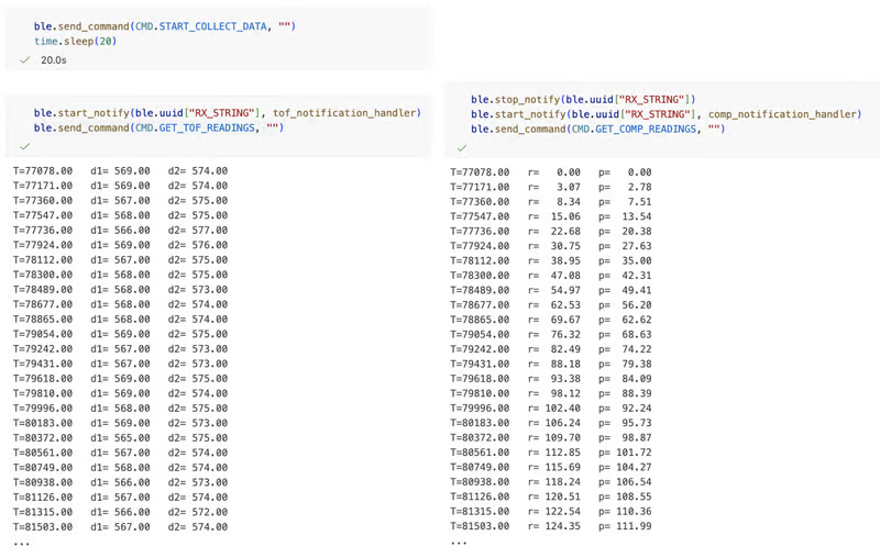
When the computer sends the START_COLLECT_DATA command, the Artemis begins recording sensor data for a fixed time interval. After the data collection period completes, the host computer sends a command (GET_TOF_READINGS or GET_COMP_READINGS) that triggers the Artemis to transmit the stored data through BLE notifications.
Also, in the main loop, I used 'if (myICM.dataReady() && distanceSensor1.checkForDataReady() && distanceSensor2.checkForDataReady())' to check if all the sensors are ready to record. This ensures the same time-stamped.
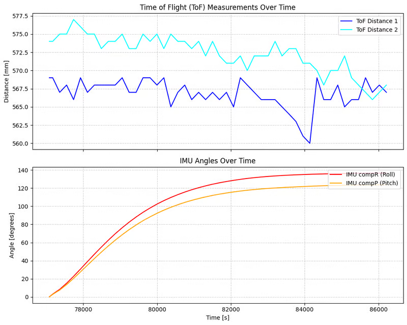
- ToF distance measurements over time.
- IMU roll and pitch angles over time.
Discussion
This lab helped me gain practical experience with soldering and hardware assembly. At the beginning, I was somewhat clumsy and often inserted wires into the wrong holes. After several attempts and corrections, I became much more comfortable and confident with soldering and wiring the sensors accurately.
I also learned how the ToF sensor uses interrupts and data-ready signals to indicate when a new measurement is available, which allows the program to avoid blocking and maintain a fast control loop.
Collabration
I referenced Lucca’s and Stephan's site for code debugging and graph formatting. I used ChatGPT to help understand xshut and i2c address and revise plot.