This lab focuses on integrating motor control hardware with the Artemis microcontroller to enable untethered robotic motion. The objective is to design a stable power and control system for DC motors using a motor driver and PWM signals while ensuring reliable operation of the microcontroller and sensors.
Pre-Lab
Battery Design
n this lab, the robot uses separate batteries for the motors and the Artemis microcontroller in order to maintain stable system performance.
When DC motors accelerate rapidly, they can draw large transient currents. If the Artemis shared the same battery as the motors, these current spikes could cause the battery voltage to momentarily drop. This voltage dip could cause the Artemis 3.3V regulator to fall below its operating threshold and potentially reset the microcontroller during operation.
Motors are also highly inductive loads. When they run—especially when driven by PWM signals—the rapid switching of current can introduce significant electrical noise and electromagnetic interference (EMI). By isolating the motor power supply from the microcontroller power supply, I can reduce the effect of this noise on the Artemis and improve overall system stability.
Motor Drivers
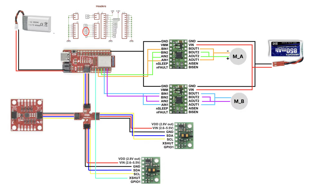
To increase the current capacity of the motor driver, I configured the two driver channels on the chip in parallel. Because both channels are on the same chip and share the same internal clock and control logic, their inputs and outputs can be safely tied together.
On the logic side, I connected:
- IN1 to IN3
- IN2 to IN4
On the output side, I connected:
- OUT1 to OUT3
- OUT2 to OUT4
This configuration effectively doubles the current capacity available for a single motor while staying within the operating limits of the driver chip.
PWM Pin Selection
I need four PWM pins to control the two motors, with two pins assigned to each motor driver for speed and direction control. Based on the RedBoard Artemis Nano pin configuration, I selected pins 4, 5, 6, and 7 because they support PWM functionality and are located next to each other on the board.
Car Setup
Here is the diagram for all the wiring:
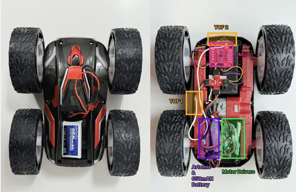
Here is the picture of all components secured in the car:
Lab
Motor Driver Setup
Because the motors experience significant vibration during operation, I needed to ensure that all electrical connections were mechanically secure. I soldered header pins to both the Artemis board and the motor driver to create reliable electrical connections. I also braided the motor wires together to increase mechanical strength and help reduce electromagnetic interference (EMI) generated by the motor currents.
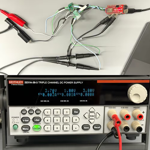
To test the motor driver outputs before connecting the motors, I connected the motor driver output pins to an oscilloscope while referencing the system ground. I powered the motor driver using an external 3.7 V power supply, which matches the voltage of the 850 mAh batteries that will be used to power the motors in later labs. This allowed me to verify that the driver produced the expected signals under realistic operating conditions
I then configured the Artemis pins as PWM outputs and used the analogWrite() function to generate PWM control signals for the motor driver:
void loop(){
    // ~25% duty cycle
    analogWrite(LEFT_MOTOR_IN1, 64);
    analogWrite(LEFT_MOTOR_IN2, 0);
    analogWrite(RIGHT_MOTOR_IN1, 64);
    analogWrite(RIGHT_MOTOR_IN2, 0);

    // ~50% duty cycle
    analogWrite(LEFT_MOTOR_IN1, 127);
    analogWrite(LEFT_MOTOR_IN2, 0);
    analogWrite(RIGHT_MOTOR_IN1, 127);
    analogWrite(RIGHT_MOTOR_IN2, 0);
}
Using the oscilloscope, I observed the PWM signals generated by the Artemis. I tested duty cycles of 25% and 50% to verify that the PWM timing matched the expected ratios.
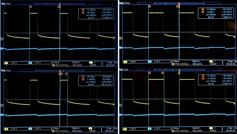
For the 25% duty cycle, the high portion of the waveform lasted approximately 1.36 ms within a total period of about 5.38 ms, which is consistent with a duty cycle $25.27%$.
For the 50% duty cycle, the high portion of the waveform lasted approximately 2.76 ms within a total period of about 5.48 ms, corresponding to roughly half of the PWM period ($50.36%$).
The complementary output signal remained near 0 V when inactive, confirming that the motor driver inputs were being driven correctly and that the PWM signals were functioning as expected.
Since the average voltage delivered to the motor is proportional to the PWM duty cycle, increasing the duty cycle increases the effective power delivered to the motor. The oscilloscope measurements demonstrates that I can regulate the power supplied to the motor through PWM control.
Motor Driver and Battery Integration
After verifying the PWM control signals, I soldered the motor driver to the battery connector to provide a stable power supply for the motors. I used an 850 mAh battery to power the motor driver while the Artemis remained powered separately.
Without external power supply, I was able to drive the motor in both forward and reverse directions. The motor responded correctly to the control signals, confirming that the driver and battery were functioning as expected.
I repeated the same process for the second motor and motor driver.
Both motors were powered using a single 850 mAh battery, and the battery was able to supply sufficient current for both motors simultaneously.
After verifying that both motors worked individually, I installed all components inside the car chassis, including the Artemis board, motor drivers, battery, and wiring. I then tested the robot by running it on the ground.
When moving forward, the robot was able to drive roughly in a straight line, although some slight deviation was present due to differences between the motors.
However, when the control algorithm commanded the robot to move in reverse, the robot did not move backward as expected. Instead, it rotated approximately 360 degrees before continuing to move forward. This behavior indicates that the motors are not perfectly balanced and that calibration of the motor speeds or PWM values will be necessary to achieve stable and symmetric motion.
PWM Operating Limits
To ensure stable motion, I experimentally determined the minimum and maximum PWM values required for each motor in both forward and reverse directions. Due to mechanical differences between the motors, the same PWM value does not always produce the same motor speed.
The experimentally determined limits are shown below:
const int FWD_LEFT_MIN = 40;  const int FWD_LEFT_MAX = 212;
const int FWD_RIGHT_MIN = 50; const int FWD_RIGHT_MAX = 255;

const int REV_LEFT_MIN = 48;  const int REV_LEFT_MAX = 210;
const int REV_RIGHT_MIN = 200;const int REV_RIGHT_MAX = 255;
Below the minimum PWM values, the motors cannot reliably overcome static friction and may fail to rotate. Above the maximum values, the motors reach saturation and small speed differences between the motors cause the robot to turn unexpectedly.
Motor Calibration
After determining the PWM limits, I implemented a calibration function that converts percentage motor commands into calibrated PWM signals. This allows the control algorithm to specify motor speeds in percentages instead of raw PWM values, while the code maps those percentages into the experimentally determined operating ranges.
void setMotors(int leftPct, int rightPct) {
  int leftPWM = 0;
  int rightPWM = 0;

  // 1. Process Left Motor
  if (leftPct > 0) {
    leftPWM = map(leftPct, 1, 100, FWD_LEFT_MIN, FWD_LEFT_MAX);
    analogWrite(LEFT_MOTOR_IN1, leftPWM);
    analogWrite(LEFT_MOTOR_IN2, 0);
  } else if (leftPct < 0) {
    leftPWM = map(abs(leftPct), 1, 100, REV_LEFT_MIN, REV_LEFT_MAX);
    analogWrite(LEFT_MOTOR_IN1, 0);
    analogWrite(LEFT_MOTOR_IN2, leftPWM);
  } else {
    // 0% = Stop
    analogWrite(LEFT_MOTOR_IN1, 0);
    analogWrite(LEFT_MOTOR_IN2, 0);
  }

  // 2. Process Right Motor
  if (rightPct > 0) {
    rightPWM = map(rightPct, 1, 100, FWD_RIGHT_MIN, FWD_RIGHT_MAX);
    analogWrite(RIGHT_MOTOR_IN1, rightPWM);
    analogWrite(RIGHT_MOTOR_IN2, 0);
  } else if (rightPct < 0) {
    rightPWM = map(abs(rightPct), 1, 100, REV_RIGHT_MIN, REV_RIGHT_MAX);
    analogWrite(RIGHT_MOTOR_IN1, 0);
    analogWrite(RIGHT_MOTOR_IN2, rightPWM);
  } else {
    // 0% = Stop
    analogWrite(RIGHT_MOTOR_IN1, 0);
    analogWrite(RIGHT_MOTOR_IN2, 0);
  }
}
void straight(int speedPct) {
setMotors(speedPct, speedPct);
}
void reverse(int speedPct) {
int revSpeed = -abs(speedPct);
setMotors(revSpeed, revSpeed);
}
void turnLeft(int speedPct) {
setMotors(-speedPct, speedPct);
}
void turnRight(int speedPct) {
setMotors(speedPct, -speedPct);
}
void stopCar() {
setMotors(0, 0);
}Using this calibration method, the robot was able to drive approximately 10 feet in a straight line at 50% PWM, demonstrating that the motor outputs were reasonably balanced after calibration.
Open-Loop Untethered Control
After calibrating the PWM ranges and implementing the percentage-based motor control function, I was able to perform open-loop, untethered control of the robot. The robot was powered entirely by its onboard battery and controlled by the Artemis without any external connections.
The control sequence commands the robot to move forward, perform 90° turns, and stop at specific intervals.
straight(50);
delay(400);

stopCar();
delay(500);

turnRight(50);
delay(430);

stopCar();
delay(500);

straight(50);
delay(400);

stopCar();
delay(500);

turnLeft(50);
delay(350);

stopCar();
delay(500);

straight(50);
delay(400);Collabration
I referenced Lucca’s and Stephan's site for code debugging and graph formatting. I used ChatGPT to help with oscilloscope and analogWrite.