This lab aims to design and validate a fast, reliable closed-loop position controller for the robot using ToF distance feedback, with the specific goal of driving toward a wall and stopping at a desired stand-off distance.
Pre-lab
Code Structure
I reorganized my Arduino program into several modular sections so that each could be developed and debugged independently.
Every single loop now handles Bluetooth communication, updates sensor readings, runs the controller when the robot is active, and stores sampled data for later transmission.
void loop()
{
   handleBLE();
   updateSensors();
   if (active && sensor_updated)
   {
       runController();
       sensor_updated = false;
   }
   if (collecting)
       collectSamples();
   if (millis() - start_sample_time >= SAMPLE_DURATION)
       stopRobot();
}
BLE Handler
To support flexible interaction between the computer and the robot, I implemented new commands as followoing:
- PING: Used to verify communication. The robot responds with “PONG”.
- START_RECORD: Initializes the system, clears previous logs, takes an initial sensor reading, and starts the control loop and data collection. This command triggers the main experiment run.
- STOP_ROBOT:Immediately stops the motors and ends the current run.
- SEND_LOG: Sends all recorded data (time, motor outputs, PID terms, IMU, and ToF readings) back to the computer for plotting and analysis.
- UPDATE_PID (kp, ki, kd): Updates the proportional, integral, and derivative gains of the controller in real time, allowing rapid tuning.
- SET_DURATION (ms): Set the duration of control run for experiment.
- SET_SETPOINT (value): Set the target value for the controller. For this lab, it corresponds to the desired distance from the wall.
- SET_MOTOR_SCALE(0-1.0): Set the percentage of power for motors.
- SET_EXTRAPOLATION: Enables or disables linear extrapolation of ToF measurements between sensor updates.
In each loop iteration, read_data() checks whether a new string has been written, and if so, handleCommand() parses the message using the RobotCommand helper class.
To start a customized control run, the host side sends the following commands:
ble.send_command(CMD.SET_DURATION, "5000")
ble.send_command(CMD.SET_SET_SETPOINT, "304")
ble.send_command(CMD.SET_MOTOR_SCALE, "0.8")
ble.send_command(CMD.UPDATE_PID, "0.2|0|0")
ble.send_command(CMD.SET_EXTRAPOLATION, "0")

ble.send_command(CMD.START_RECORD, "")
During experiment run, Artemis stores sampled values in arrays. When the robot stops, the computer can send the SEND_LOG command, which iterates through the buffers, formats, and sends to the Python side.
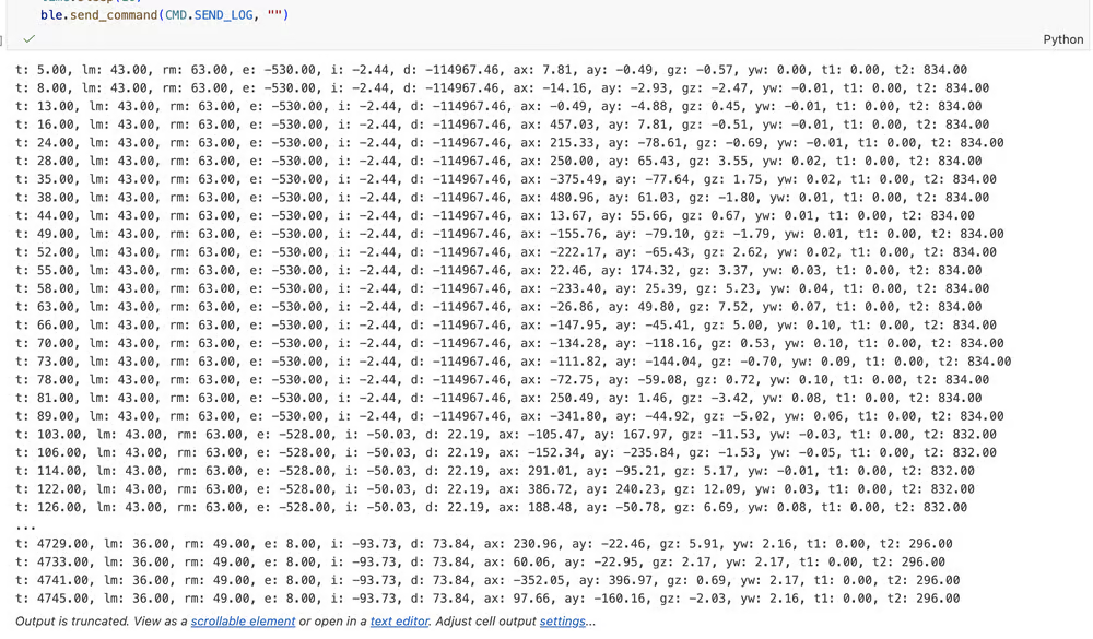
For safety and robustness, I also implemented a hard stop directly on the Artemis. If the Bluetooth connection is lost while the robot is active, the code detects the disconnection in handleBLE() and immediately calls stopRobot() to shut off the motors. In addition, the control run automatically terminates after the specified sample duration.
Position Control
The position controller was implemented in runController(). At each control step, the code computes the current distance error from the ToF sensor, updates the integral and derivative terms, and then forms the control output using the PID equation. The resulting output is then saturated and passed to applyOutput()
void runController()
{
    unsigned long current_control_time = micros();
    float dt = (current_control_time - last_control_time) / 1.e6;
    if (dt <= 0.0f) return;
    last_control_time = current_control_time;

    sensor_value = getSensorValue();
    float new_error = setpoint - sensor_value;

    integral_value += new_error * dt;
    derivative_value = (new_error - error_value) / dt;

    output_value = kp * new_error + ki * integral_value + kd * derivative_value;
    error_value = new_error;

    applyOutput(output_value);
}

void applyOutput(float output)
{
    float power = -output;
    power = power * MOTOR_SCALE;
    if (power > output_limit)
        power = output_limit;
    if (power < -output_limit)
        power = -output_limit;

    power = -MAX_MOTOR_PCT;
    left_motor_pct = power;
    right_motor_pct = power;
    setMotors(power, power);
}
Before tuning the full PID controller, I estimated a reasonable range for the proportional gain.
In my implementation, the controller computes the error as the difference between the desired stand-off distance and the measured ToF distance, then converts that error into a motor command through the PID equation.
If the robot starts about 2–4 m from the wall and the target setpoint is 304 mm, then K_p should be about 100/2000 = 0.05 motor-percent per millimeter to enable the car to reach its maximum speed at the start.
P-Controller Test
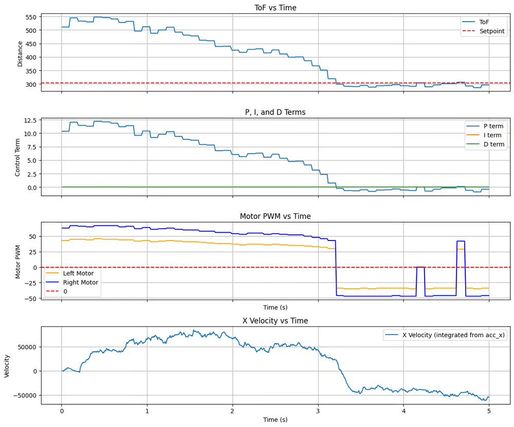
I first set K_p = 0.025, K_i = 0, and K_d = 0, so the controller reduces to u = K_p e. The controller was tested at full motor scale (1.0), with a setpoint of 304 mm, under two different initial distances: 2 m and 4 m, each with a 5 s duration.
Test 1: 2m Initial Distance
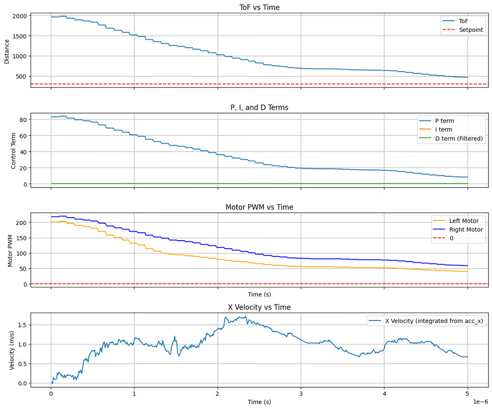
The robot approaches the wall smoothly and reaches the desired setpoint without significant overshoot. The maximum velocity reaches approximately 1.75 m/s. However, a small steady-state error remains due to motor deadband and friction.
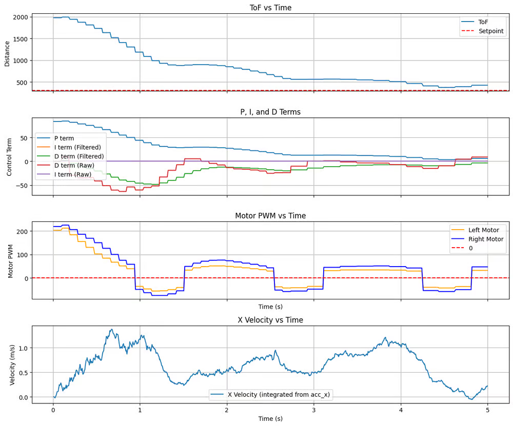
Test 2: 4m Initial Distance
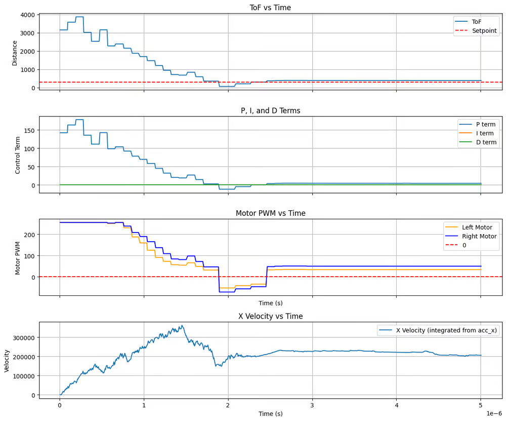
The robot exhibits noticeable overshoot near the setpoint. Because the initial error is much larger, P-controller generates a high motor power for a longer period, building up momentum. So, the robot cannot decelerate quickly enough as it approaches the targets.
TOF Mode
To diminish the overshoot observed in P-control, I first investigated whether reducing sensing delay could improve system responsiveness. In the previous experiments, the ToF sensor was configured in long-distance mode, which provides a larger sensing range but lower update frequency.
For the 5 s duration tests, the collected statistics are shown below:
| Loop Count | TOF Count | IMU Count | P-Control Count | |
|---|---|---|---|---|
| 2m | 1169 | 47 | 1390 | 48 |
| 4m | 1075 | 36 | 1296 | 37 |
This corresponds to a ToF update frequency of approximately 7–10 Hz, which becomes even lower at larger distances. Since the controller is only updated when a new ToF reading is available, the low sensor rate introduces significant delay. As a result, the robot cannot react quickly enough to changes in distance and overshoot.
To address this, I switched the sensor to short-distance mode, which is expected to provide higher update frequency at the cost of reduced sensing range.
| Loop Count | TOF Count | IMU Count | P-Control Count | |
|---|---|---|---|---|
| 2m | 901 | 53 | 1101 | 54 |
| 4m | 939 | 53 | 1144 | 54 |
With short mode, the ToF frequency increases to approximately ~11 Hz, leading to more frequent controller updates.
In the 2m case, this improves performance: the robot exhibits reduced steady-state error and better tracking near the setpoint due to more responsive feedback.
In the 4m case, however,the ToF readings become inaccurate, causing the robot to misinterpret its distance to the wall and stops midway.
Therefore a result, I chose to continue using long-distance mode, and instead focus on improving control performance through algorithmic methods.
PD-Controller
To address the overshoot observed in proportional control, I added a derivative term to the controller. The derivative term provides a damping effect by penalizing rapid changes in distance, allowing the controller to predict motion and slow down earlier.
In the runController() function, I modified the derivative computation to avoid derivative kick by taking the derivative of the measurement instead of the error:
    // Avoid derivative Kick
    derivative_value = -(new_sensor - sensor_value) / dt;
Additionally, since the ToF sensor is noisy and has relatively low update frequency, I applied a low-pass filter (LPF) to the derivative term to improve stability:
    // Derivative LPF
    derivative_value = derivative_filter_alpha * derivative_value + (1.0f - derivative_filter_alpha) * last_derivative_value;
After tuning, I found that K_p = 0.05 and K_d = 0.05 provide good performance across both test cases. The controller was tested at full motor scale (1.0), with a setpoint of 304 mm, under two different initial distances (2m and 4m) over a 5 s duration.
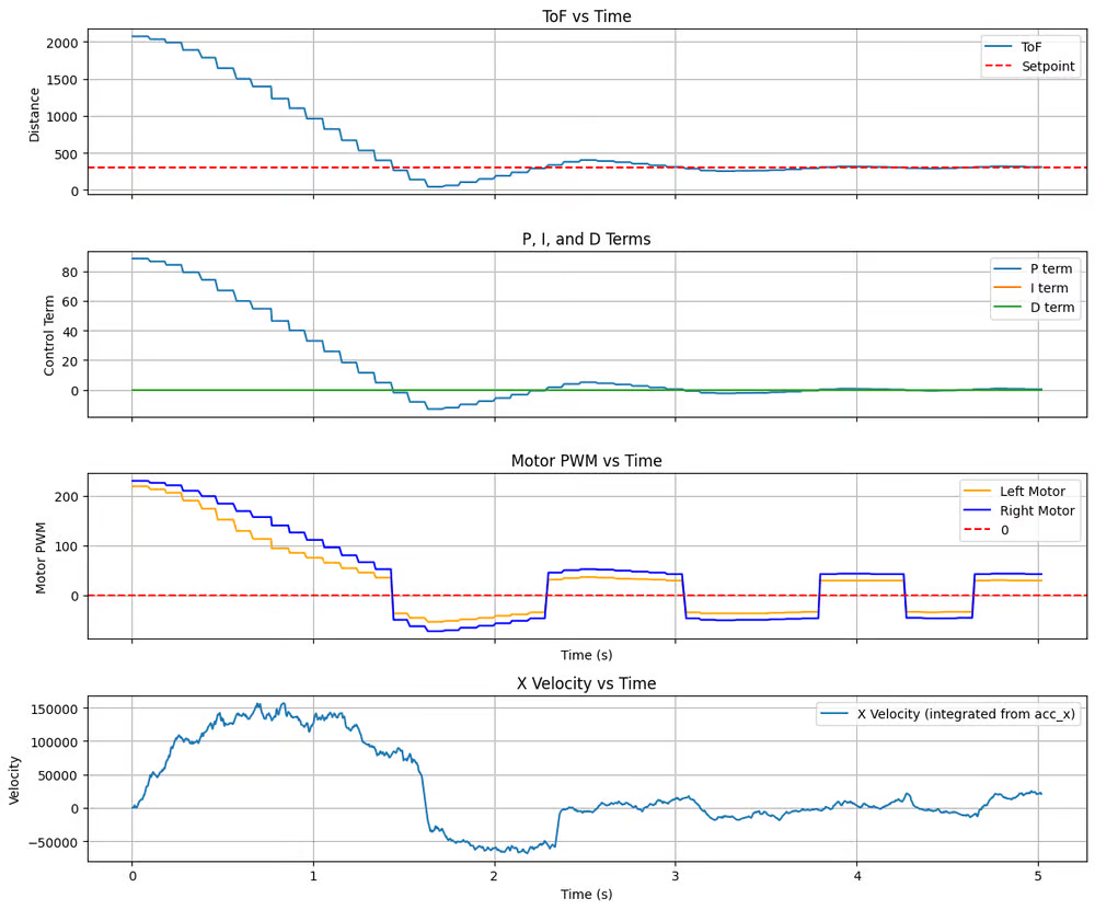
Test 1: 2m Initial Distance
With the addition of derivative term, the robot approaches the setpoint more smoothly, with reduced oscillation, minimal overshoot, and smaller steady-state error.
Test 2: 4m Initial Distance
Compared to the large overshoot observed under P control, the PD controller is able to reduce overshoot substantially. Although some oscillation remains due to sensing delay and motor dynamics, the system is much more stable and converges closer to the desired setpoint.
Extrapolation
To further reduce the effect of sensing delay, I implemented linear extrapolation of the ToF distance. Instead of waiting for the next sensor update, the controller estimates the current distance using the most recent velocity estimate.
Specifically, I removed the requirement that the controller only runs when a new sensor reading is available:
void loop()
{
    handleBLE();
    updateSensors();
    if (active)
        runController();

    if (collecting)
        collectSamples();
    if (millis() - start_sample_time >= SAMPLE_DURATION)
        stopRobot();
}
The sensor value used by the controller is then computed using linear extrapolation. Here, tof2_velocity is computed from the last two ToF measurements.
float getSensorValue(){
    unsigned long current_time = micros();
    float extrapolated_dist = tof2_dist + tof2_velocity * ((current_time - tof2_time) / 1.e6);
    return extrapolated_dist;
}
Test 1: 2m Initial Distance
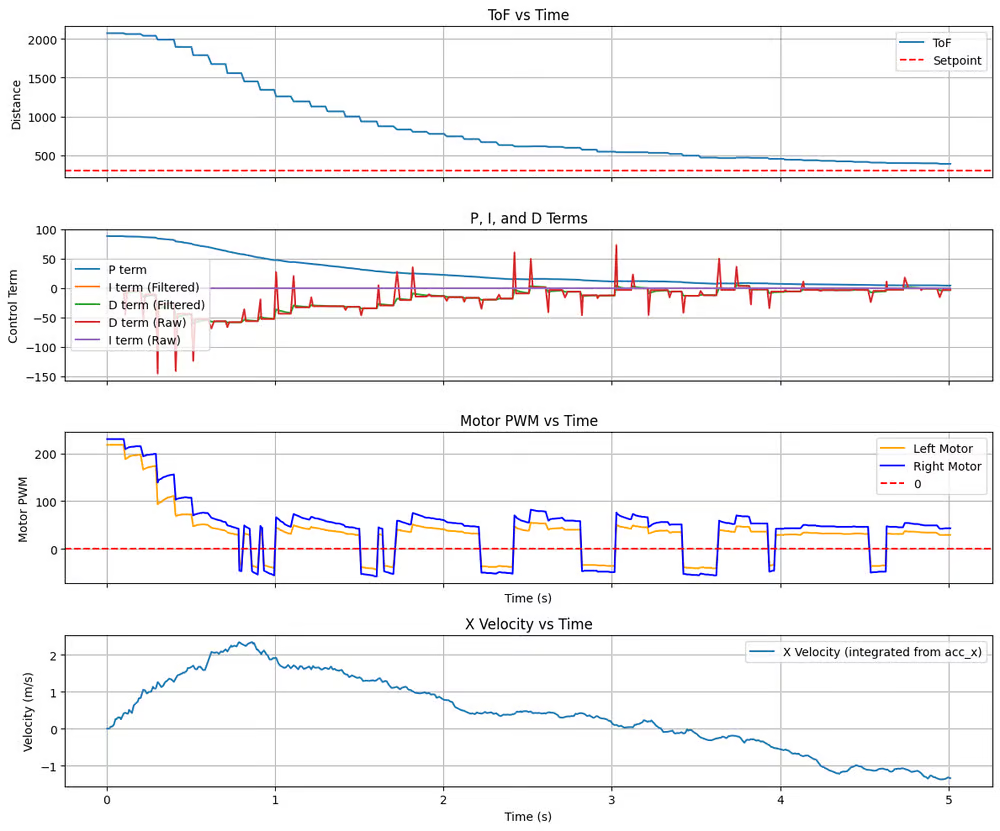
The robot exhibits a smoother and more continuous approach toward the setpoint, with less staircase-like behavior compared to the sensor-limited case.
However, the derivative term shows noticeable high-frequency fluctuations due to noise in the velocity estimation, which occasionally leads to small oscillations in the motor command.
Despite this, the overall trajectory remains stable, and the robot is able to decelerate earlier and track the setpoint more accurately.
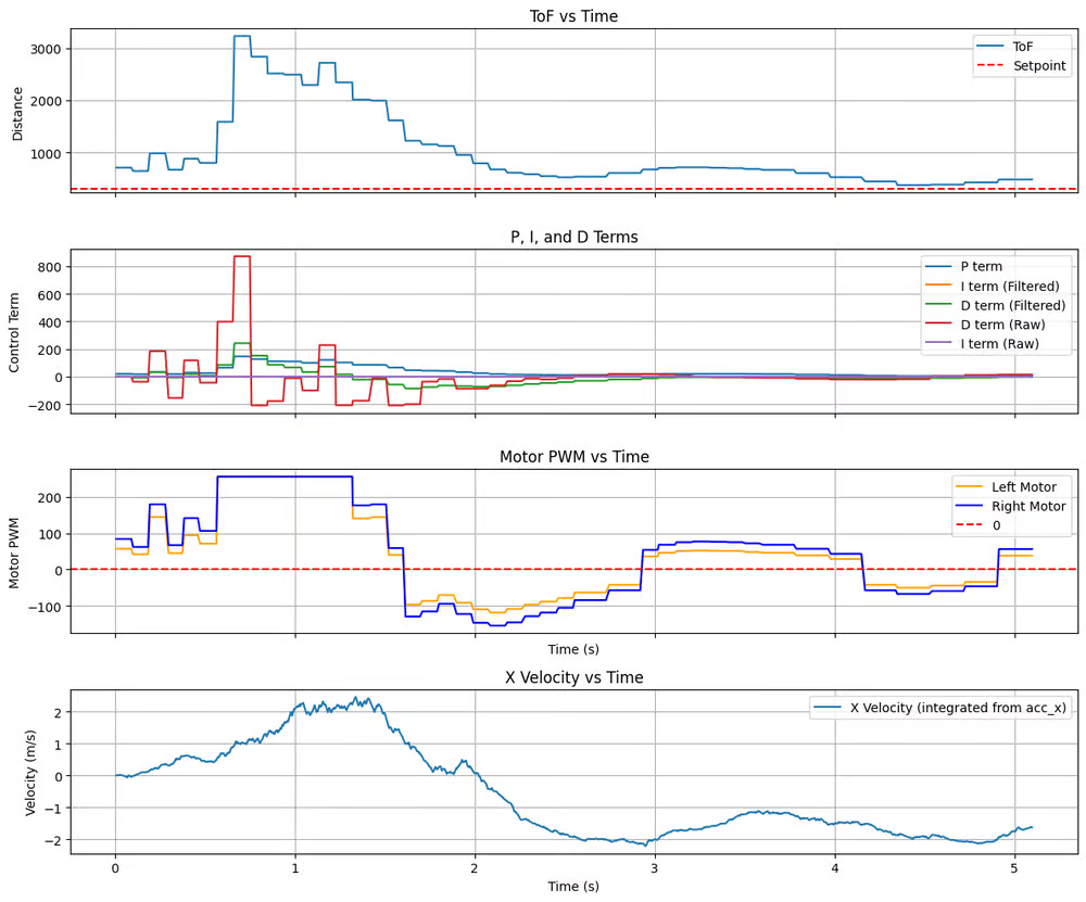
Test 2: 4m Initial Distance
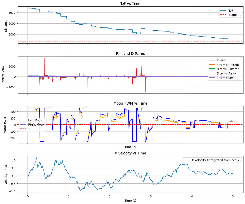
Same with 2m case, the ToF plot shows a more continuous decrease in distance, indicating reduced delay. However, the derivative term exhibits very large spikes (on the order of ±2000), resulting in aggressive switching between forward and reverse PWM values.
Frequency
| Loop Count | TOF Count | IMU Count | PD-Control Count | |
|---|---|---|---|---|
| 2m | 448 | 50 | 583 | 448 |
| 4m | 510 | 50 | 640 | 510 |
Now, the ToF sensor updates at approximately ~10 Hz, while the controller runs at ~90–100 Hz, which is nearly 10× faster than the sensor update rate.
With extrapolation enabled, the controller is no longer limited by the ToF update frequency. It successfully improves responsiveness at the cost of increased sensitivity to noise.
Discussion
A steady-state error of approximately 100 mm remains. This may be addressed in the future by adding an integral term (PID control) to compensate for bias caused by motor deadband and friction.
Additionally, the robot struggles to maintain a straight trajectory over long distances (e.g., 4m). IMU-based heading correction or other orientation controller are needed to fix this.