The objective of this lab is to design, implement, and evaluate an orientation controller for the robot using the IMU, specifically by estimating yaw from gyroscope data and applying a P/PI/PD/PID-style controller to command differential motor motion for in-place rotation.
Pre-lab
The overall software architecture and Bluetooth communication framework in this lab follow the same structure developed in Lab 5. The robot uses a bidirectional BLE interface to receive commands from a host computer and transmit logged sensor and control data back for analysis.
Compared to Lab 5, I introduce an additional abstraction layer through ControlMode, allowing the robot to switch between different feedback strategies. Specifically, a new command SET_MODE is implemented to toggle between:
- MODE_POSITION: uses ToF distance measurements as feedback.
- MODE_ORIENTATION: uses IMU-derived yaw (from gyroscope integration) as feedback.
PID Input Signal
The primary input to the orientation controller is the robot’s yaw angle, which can be estimated from IMU measurements. A gyroscope directly measures angular velocity (deg/s), so numerical integration is required to recover orientation:
unsigned long current_imu_time = micros();
float dt = (current_imu_time - last_imu_time) / 1.e6;
gyr_z = myICM.gyrZ();
gyr_yaw += (gyr_z - gyr_bias_z) * dt;
However, this approach introduces Bias drift. Even a small constant bias in the gyroscope accumulates over time, leading to large orientation error.
DMP
The IMU provides a built-in Digital Motion Processor (DMP), which performs sensor fusion internally and outputs a more stable orientation estimate. Compared to raw integration, the DMP significantly reduces drift by combining gyroscope and accelerometer data.
I found github manual about the nvenSense Digital Motion Processor.
To enable DMP, I uncomment the line 29 of ICM_20948_C.h in the SparkFun_9DoF_IMU_Breakout_-_ICM_20948_-_Arduino_Library..
#define ICM_20948_USE_DMPThen, I loaded and started DMP during the initialization of IMU. And it is set to INV_ICM20948_SENSOR_GAME_ROTATION_VECTOR to output a 32-bit, 6-axis quaternion that reperesents yaw. Also, I configured the sample rate to maximum ($255 Hz$) with myICM.setDMPODRrate(DMP_ODR_Reg_Quat6, 0). Here is the full code:
void setupIMU()
{
    //...
    // IMU initialization
    //...

    SERIAL_PORT.println("Initializing DMP...");
    bool success = true;
    // Initialize the DMP. initializeDMP is a weak function. You can overwrite it if you want to e.g. to change the sample rate
    success &= (myICM.initializeDMP() == ICM_20948_Stat_Ok);
    // Enable the DMP orientation sensor
    success &= (myICM.enableDMPSensor(INV_ICM20948_SENSOR_GAME_ROTATION_VECTOR) == ICM_20948_Stat_Ok);
    // Set DMP ODR to to the maximum
    success &= (myICM.setDMPODRrate(DMP_ODR_Reg_Quat6, 0) == ICM_20948_Stat_Ok);
    // Enable the FIFO
    success &= (myICM.enableFIFO() == ICM_20948_Stat_Ok);
    // Enable the DMP
    success &= (myICM.enableDMP() == ICM_20948_Stat_Ok);
    // Reset DMP
    success &= (myICM.resetDMP() == ICM_20948_Stat_Ok);
    // Reset FIFO
    success &= (myICM.resetFIFO() == ICM_20948_Stat_Ok);
    // Check success
    if (success)
        SERIAL_PORT.println(F("DMP enabled!"));
    else
        SERIAL_PORT.println("DMP initialization failed!");

}
After initialisation, the DMP stores the computed result in the FIFO (First-In-First-Out) cache. Therefore, each time the loop() is executed, the stored data must be retrieved using myICM.readDMPdataFromFIFO(data). Then, I transfer it to yaw with the following equations:
bool updateIMU()
{
    if (myICM.dataReady())
    {
        myICM.getAGMT();
        acc_x = myICM.accX();
        gyr_z = myICM.gyrZ() - gyr_z_offset;
    }

    icm_20948_DMP_data_t data;
    myICM.readDMPdataFromFIFO(&data);
    if ((myICM.status == ICM_20948_Stat_Ok) || (myICM.status == ICM_20948_Stat_FIFOMoreDataAvail))
    {
        if ((data.header & DMP_header_bitmap_Quat6) > 0)
        {
            double q1 = ((double)data.Quat6.Data.Q1) / 1073741824.0; // X
            double q2 = ((double)data.Quat6.Data.Q2) / 1073741824.0; // Y
            double q3 = ((double)data.Quat6.Data.Q3) / 1073741824.0; // Z

            double q0_sq = 1.0 - ((q1 * q1) + (q2 * q2) + (q3 * q3));
            if (q0_sq < 0.0)
                q0_sq = 0.0;
            double q0 = sqrt(q0_sq); // W
            dmp_yaw = atan2(2.0 * (q0 * q3 + q1 * q2), 1.0 - 2.0 * (q2 * q2 + q3 * q3)) * 180.0 / PI;

            imu_count++;

            return true;
        }
    }
    return false;
}
Sampling Time
According to the ICM-20948 datashee, the gyroscope full-scale range (FSR) can be configured to ±250, ±500, ±1000, or ±2000 deg/s with GYRO_FS_SEL. When using the DMP, the default configuration sets the FSR to ±2000 deg/s.
This corresponds to a maximum measurable angular velocity of approximately ±2000 °/s (≈ ±34.9 rad/s), which is sufficient for our application. In practice, this allows the robot to rotate $5$ times per second without saturating the sensor.
Range
The yaw angle derived from the DMP is a continuous angle system. I wrote a helper function function to strictly limit the target error to the range between $-180^\circ$ and $+180^\circ$.
float wrapAngle180(float angle)
{
    while (angle > 180.0f)
        angle -= 360.0f;
    while (angle < -180.0f)
        angle += 360.0f;
    return angle;
}
PID Algorithm
To make the robot turn in place, I command the left and right wheels with equal magnitudes but opposite directions.
void applyOutput(float output)
{
    if (control_mode == MODE_ORIENTATION)
    {
        left_motor_pct = power;
        right_motor_pct = -power;
        setMotors(power, -power);
    }
}
The PID controller output is therefore interpreted as the turning command sent to the differential drive. A positive output rotates the robot in one direction, while a negative output rotates it in the opposite direction. The orientation controller is implemented as follows:
void runController()
{

    case MODE_ORIENTATION:
    {
        float new_sensor = wrapAngle180(getSensorValue(dt) - yaw_offset);
        float new_error = wrapAngle180(new_sensor - setpoint);

        // Avoid derivative Kick
        float delta_angle = wrapAngle180(new_sensor - sensor_value);
        raw_derivative_value = delta_angle / dt;
        // Derivative LPF
        derivative_value = derivative_filter_alpha * raw_derivative_value + (1.0f - derivative_filter_alpha) * derivative_value;
        // Anti-Windup
        raw_integral_value = integral_value + new_error * dt;
        float new_integral = constrain(raw_integral_value, -integral_limit, integral_limit);

        float unsat_output = kp * new_error + ki * new_integral + kd * derivative_value;
        bool saturated_high = unsat_output > output_limit;
        bool saturated_low = unsat_output < -output_limit;
        if ((!saturated_high && !saturated_low) || (saturated_high && new_error < 0) || (saturated_low && integral_valuenew_error > 0))
        {
             = new_integral;
        }
        output_value = kp * new_error + ki * integral_value + kd * derivative_value;
        error_value = new_error;
        sensor_value = new_sensor;
        applyOutput(output_value);
        break;
    }
}
Derivative Term
The derivative term is computed from the yaw estimate produced by the DMP. Although the yaw itself is obtained from integrated inertial measurements, using its change over time is still reasonable in practice because the DMP output has already been filtered through onboard sensor fusion.
Compared to directly differentiating noisy raw gyroscope measurements, the DMP-based yaw signal is much smoother and more stable for feedback control.
A major concern in PID design is derivative kick. If the derivative term is computed directly from the error, then a sudden setpoint change causes an instantaneous jump in error, which produces a large derivative spike and results in an aggressive motor command.
To avoid this, I compute the derivative using only the change in the measured yaw angle, excluding the setpoint from the derivative calculation. As a result, abrupt changes in the desired orientation do not immediately generate a large derivative response. The derivative term instead reflects the robot’s actual angular motion。
// Avoid derivative Kick
float delta_angle = wrapAngle180(new_sensor - sensor_value);
raw_derivative_value = delta_angle / dt;
Since differentiation amplifies high-frequency noise, I further apply a low-pass filter to the raw derivative term. This suppresses sudden spikes and makes the D term more stable.
// Derivative LPF
derivative_value = derivative_filter_alpha * raw_derivative_value + (1.0f - derivative_filter_alpha) * derivative_value;
Integrate Term
The integral term is used to eliminate residual steady-state error, but it can also create problems if allowed to grow without bound.
When the robot encounters a large sudden change in the setpoint, or when its wheels become stuck, the error persists for a long time.
Without anti-windup, the integral term will continuously accumulate this error, resulting in an extremely large control signal. Even after the robot approaches the target angle, the stored integral term continues driving the motors strongly, causing overshoot and slower recovery.
To prevent this, I use two forms of anti-windup. First, I explicitly clamp the integral state within a fixed bound using constrain(). Second, I only update the integral term when the controller output is not saturated, or when the error direction would help bring the output back out of saturation.
// Anti-Windup
raw_integral_value = integral_value + new_error * dt;
float new_integral = constrain(raw_integral_value, -integral_limit, integral_limit);

float unsat_output = kp * new_error + ki * new_integral + kd * derivative_value;
bool saturated_high = unsat_output > output_limit;
bool saturated_low = unsat_output < -output_limit;
if ((!saturated_high && !saturated_low) || (saturated_high && new_error < 0) || (saturated_low && integral_valuenew_error > 0))
{
        = new_integral;
}
P-Control
I started with P-Controller and got the best result when $K_p =1.5, K_i=0, K_d=0$. With these parameters, I tested for two times.
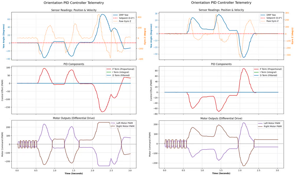
In both tests, the car was able to react to the error and move back towards the setpoint (0°), but there were problems with both.
-
Left: there is an overshoot between 2.5 and 3.0 seconds.
-
Right: there is a steady-state error caused by static friction. Between 1.0 and 1.3 seconds, the yaw angle remains at around 7 degrees and the corresponding motor PWM is around 60, which is insufficient to overcome the static friction of the wheels.
PD-Control
To solve the overshoot, I introduced the derivative term, achieving the best tuning with $K_p =1.5, K_i=0, K_d=0.25$.
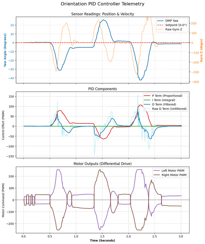
According to the plot, the overshoot problem has been solved. Even if it started at -40°, it returned to 0 with no oscillation.
However, the steady-state error still exists. Between 1.0 and 1.5 seconds, the DMP yaw remains at -5 degrees, while the motor PWM stays at 40–50%.
PID-Control
To elimiate the steady-state error, I added the integrate term, achieving the best tuning with $K_p =1.5, K_i=1.2, K_d=0.25$.
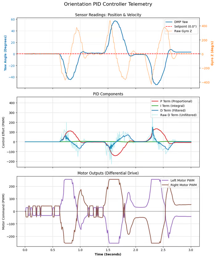
The steady-state error is resolved. No matter how far it is knocked (even reaching +60 degrees at 1.5 seconds), it always ends up landing steadily and precisely on the target orientation.
Discussion
Orientation PID is crucial for future applications:
- Navigation: In reality, the friction on the left and right wheels of a motor is unpredictable. Without intervention, the robot will inevitably deviate from its intended path. Future navigation systems will need to not only make precise turns in place but also maintain a straight course.
- Stunts: To do drift, we can set the orientation target to $360^\circ$ while moving forward.
To add orientation control while the robot is driving forward or backward, a mixer is needed to add the forward speed and the turning speed together.
left_motor_pct = forward_speed + turn_power;
right_motor_pct = forward_speed - turn_power;
Also, we need to real-time update the setpoint. In future maze navigation or path planning, a robot cannot stop and restart every time it turns. It needs to dynamically receive a series of waypoints.
My system architecture already supports this. Using the BLE SET_SETPOINT command, the host computer (Python) can instantly send the new target angle to the microcontroller while the robot is running at full speed. The PID controller will adapt and immediately calculate the new error, driving the robot to turn toward the next target.